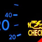
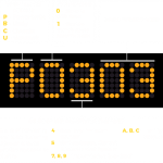
Identifying a DTC code is easier than you might think, and there are a few steps you can take to learn how to read this information. First, you must understand how a DTC code is interpreted. Generally, there are five distinct characters in the code, with the third character being a digit ranging from 1 to 8. The fourth and fifth characters are two-digit numbers between 0 and 99, and are called fault indexes.
These fault indexes identify the issue specific to your vehicle. You can also consult your vehicle’s manual or manufacturer for more detailed explanations. Thankfully, there are some tools available online that make reading and understanding a DTC code much easier.
Identifying a specific fault index
Identifying a specific fault index using the DTC code of your vehicle can help you diagnose problems that occur before your vehicle experiences a complete breakdown. These codes are not always accurate, though; a P030X code will only indicate that a cylinder is misfiring. Nevertheless, this technology is a tremendous advantage for vehicle owners, both for their repair and maintenance needs.
Generally, DTCs fall into one of four states: Clear, Pending, and Active. The Clear state is one with no fault conditions, while the Pending state indicates fault conditions and must persist until the system is confirmed. A DTC that is in an active state, on the other hand, must be able to return to a fault condition. Therefore, it is important to check the status of your vehicle when you encounter this code and take action before it gets any worse.
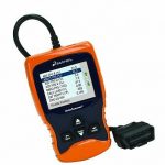
For more information on a particular fault index, you can consult the manufacturer’s website or the standard DTC list for your vehicle. Additionally, robust fleet management solutions can provide complete code definitions and fault alerts. Unlike basic code readers, these tools plug into the 16-pin OBD-II diagnostic connector, located in the left side of the steering column. They can also be used on pre-1996 vehicles, though these vehicles may need special adapters to connect to the car’s OBD-II connector.
The second-most important factor when determining the cause of an EGR problem is understanding the DTC code. The generic codes are applicable to any type of car, while manufacturer-specific codes are meant to be addressed by the manufacturer. Manufacturer-specific codes have the fourth and fifth digits, which are known as the “Specific Fault Index”. This indicates that the fault is specific to the vehicle and is not a generic issue.
A typical DTC code is two digits long. The first letter identifies the category, while the second two digits define the type of problem the car is experiencing. The P0782 code, for example, indicates that an issue is with the powertrain, but the second digit, the “green” digit, indicates that the code is a generic fault. The green digit informs the technician if the fault index is generic or if the code is a specific one.
The diagnostic trouble codes, or DTCs, are a key part of a vehicle’s onboard computer. When one of these sensors is out of spec, the on-board computer’s fault detection system stores the code. It can also help you diagnose a problem. The Society of Automotive Engineers has a fault manual that explains all of the possible causes of an ECU failure.
Using a scan tool, which has Bluetooth or Wi-Fi, allows you to view the DTC fault code. Once you’ve logged in to a service portal, you can view the information the scan tool provides. Some devices can even send the code directly to a computer or smartphone for further analysis. Once you have the information, you can then make a plan of action based on this information.
Color-coding the severity of the fault index
The UDSCS is a standard used by many stakeholders to classify a fault. The system is modeled after the global color coding of traffic signals and incorporates yellow instead of amber. Yellow is one of the three primary colors and has a particular name in every language. Black and purple are also included, representing higher severity levels and non-destructive events. This system is highly adaptable and is a proven means of communicating the level of a fault.
Using a standardized colour-coding system for criticality levels could have many implications, from clinical practice to adverse event reporting systems. It’s important to remember that the severity of a fault is not the same in all situations. Colour-coding the severity of a fault can help clinicians understand when a fault is a high-risk situation and how to respond accordingly. It also has the potential to increase communication between clinicians and manufacturers of products.
When determining a fault’s severity, the UDSCS methodology combines qualitative measures and quantitative measurements to derive a numerical ranking of its impact. For instance, if an earthquake were to strike a building, the UDSCS level 0 would result in no damage. In the case of a simulated earthquake, the severity levels could range from a mild to an extreme event. The severity levels of the fault index can be estimated with some degree of accuracy, which is critical for public reporting and planning. The corresponding contingency size should be appropriately sized and the recovery process can begin in earnest.
Getting real-time data from a vehicle’s onboard diagnostic system
Modern implementations of a vehicle’s onboard diagnostic system (OBD) are able to provide real-time data, including fault codes, which can be useful in troubleshooting a car. These codes can be read from a mobile device with Bluetooth or USB connectivity. This data can help vehicle owners to understand their car’s condition and prevent a potentially dangerous problem from occurring.
Traditionally, auto enthusiasts have installed additional gauges to monitor the car’s performance, but thanks to the OBD standard interface, these are now available on enthusiast instrumentation systems. Using specialized software, auto enthusiasts can monitor the performance of their cars and reduce their insurance premiums. They can also monitor the behavior of their fleet drivers to improve safety and reduce insurance costs. To get started, download the Windmill software and start using it in your vehicle.
Getting real-time data from a car’s onboard diagnostic system is vital to diagnosis powertrain problems. A check engine light is triggered by several different components, including a faulty sensor or bad wiring. Getting live data from a vehicle’s OBD2 can help you determine which component is causing the check engine light to come on. Moreover, it can help you identify the conditions that led to the emergence of a diagnostic trouble code.
In addition to being essential to vehicle repair, the information collected by the OBD-II is important in telematics. Some of these services are popular with automobile insurance companies, such as Pay-As-You-Drive. With OBD-II data, vehicle owners can easily track the performance of their cars and receive alerts about potential problems. Moreover, it also helps improve first-responder dispatch efficiency.
Real-time parameters include RPM, speed, pedal position, fuel level, spark advance, airflow rate, and coolant temperature. The data can also be obtained from the SAE J1979 standard. Further, if a vehicle owner wants to check a specific parameter, he can use the proprietary PIDs of the carmaker. However, it is important to note that OBD-II parameters are only available to OBD-II-certified test equipment.
When using an onboard diagnostics system, it is vital to have a backup plan. Most carmakers are developing applications for this technology that can provide more value to drivers. One such application is fleet management systems. If a vehicle has an airbag deployment, the car will call 911 and give a list of problems. This information gives the technician a head start when fixing the car.
The onboard diagnostics (OBD) protocol is an evolving standard for automotive diagnostics. The EOBD protocol is mandatory in the European Union and will be required in all new gasoline and diesel cars starting in 2008. In the US, however, all vehicles will implement OBDII through a Controller Area Network, which is defined by ISO 15765-4. In addition to being standardized, these systems have also increased in complexity. By using this technology, mechanics can identify malfunction indicator lights before they become a bigger problem.


