
For those who dream about being able to see a waveform, rather than a little window containing digits on a multimeter, this second part to the oscilloscope story will attempt to unravel the mystery of transforming a regular laptop, with its unlimited capabilities, into a powerful oscilloscope.
It can be done, plus some extras, by simply combining it with a USB-based digital storage processor, creating a powerful duo that combines the features of a computer with the abilities of an oscilloscope .
For the purpose of this article, the DSO processor-2150- DSO meaning a modern digital storage oscilloscope – was sourced from the internet (convenience rather than preference) to illustrate how seamlessly the laptop and a DSO can dovetail to operate as a powerful duo.
This combination has many advantages:
- The unit is portable. It can be placed on the car, in the car and under a car.
- The laptop’s battery pack supports the DSO and it can be used while test driving.
- The information can be stored and analysed on the laptop and it can transfer information.
- The information builds up a historical database for the whole workshop team to share.
- It can be a great marketing tool to demonstrate to your customers the problems and the solutions.
This powerful combination, like all computers , is probably more limited by the operator than the equipment.
But for now, the focus is on the hardware which involves measuring the signal at the tip of the probe.
The signal travels along the coaxial cable and is processed by the DSO that supports a communication protocol between itself and the laptop’s USB ports, thereby displaying a precise replica of a measured signal.
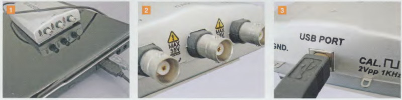
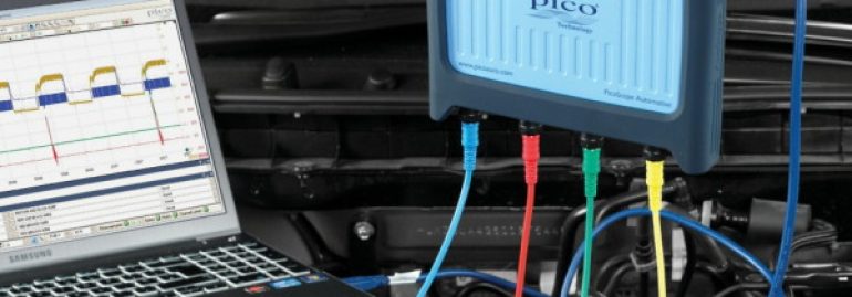
A USB-based DSO is often contained in a small and very light case, ideal for piggybacking on the back of a laptop with double-sided sticky tape, immediately turning it into a powerful duo (pic 1).
Built into the case is a state-of-the-art dual channel processor that converts an incoming signal into patterns, virtually two DSOs for the price of one.
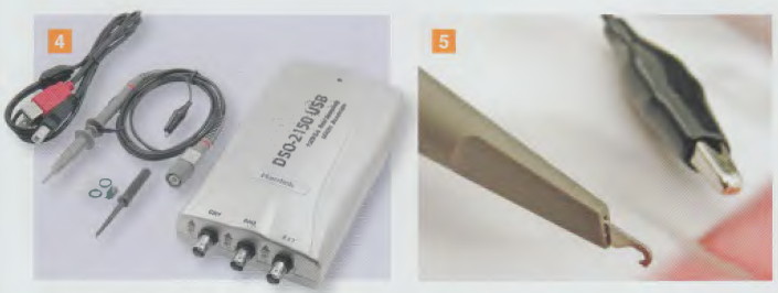
This is referred to as a dual channel display DSO (channel1 and 2) with external trigger (pic 2). Two waveforms can be displayed at the same time and they can be superimposed, stretched and squeezed. For now, the focus should stay on the processor.
Unlike a digital multimeter where incoming signals are displayed as digits, this processor digitises any automotive signal by chopping the signal 150 million times (or samples) every second.
However, in order to synchronise the laptop’s screen display with the processor’s chopping-up sequence, a program on a mini CD is downloaded to the laptop via the USB port (pic 3) enabling the powerful duo to function in harmony.
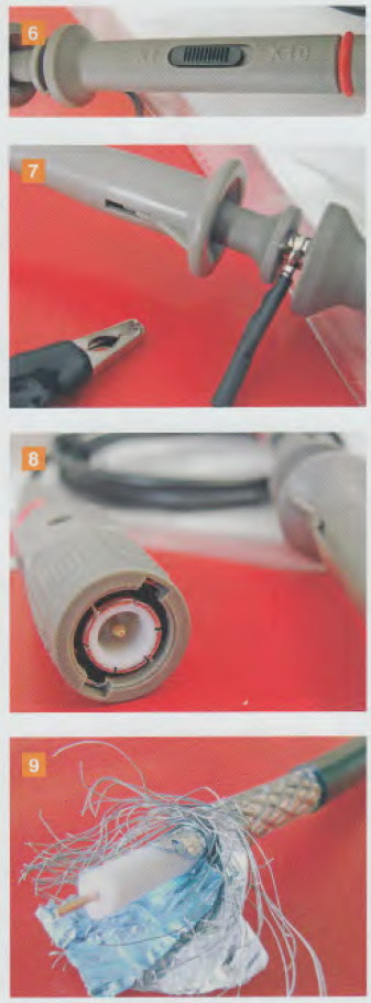
The DS0-2150 package (pic 4) contains a user manual, two probes, a calibrating tool kit, a mini CD and the processor.This package of components work together to display the measured waveform in its true and unadulterated original form, with no distortions or extraneous noises.
A probe could be as simple as a piece of conducting electrical wire with a sharp tip. It could be placed on the component that carries the signal to the processor.
However,the design principle of a probe with its alligator clip (pic 5) is much more involved than a piece of electrical wire.
The probe has an attenuator that can be switched from X1 to X10 (pic 6). This is done by moving the slider switch one way or the other,thus attenuating the incoming signal by either 10 to one (X10) or one to one(X1) .
Assume you are measuring a waveform of an inductive circuit like an injector, ignition coil or even a vacuum switching valve solenoid. The chances are that the spikes generated by the inductive circuit (back electromotive force or EMF) will need to be attenuated by 10 to one so the waveform can be squeezed onto the screen (more on that in a future article that will cover scales of the X axis andY axis).
For now, we return to the probe’s earthing alligator clip (pic 7) and the shielded BNC connector (pic 8). This connector is named after its inventor Bayonet Neiii-Concelman and was designed to provide maximum immunisation against noise when the shielded cable is connected to its mating connector with a quarter turn of the coupling nut.
Why is shielded cable used?
You might not realise this, but right now, as you occupy a space in time, the chances are high that you are being bombarded with zillions of electromagnetic wave radiations (EM waves), and unless you are physically in a Faraday cage (rendering you immune to EM waves) you are being induced by the waves and generating an induced voltage similar to that of the rod of a vehicle ‘s radio antennae.
If this induced voltage was analysed, it would be a compilation of myriad encoded EM signals. Indeed, any conducting material bombarded by EM waves will generate a voltage based on the length of the conductive material and will be proportional to the strength of the electromagnetic field.
Using the analogy of the antennae rod, this induced voltage will travel from the base of the rod (as minute as it may be) via a cable to the radio head unit, the signal is decoded and presto, the sound of music.
The minute signal attempting to travel along the antennae cable is, in effect, trying to reach the radio head unit without any added induced EM waves . Along the way, it will encounter a heavy bombardment from powerful EM waves generated by the secondary ignition coils such as alternators and DC motors.
The challenge is to immunise the conductive antennae cable, shielding it from unwanted and swamping bombardments.
This is done by building a cage along the conductive wire. The cage captures the unwanted radiation and sinks it to the vehicle’s earth potential (ground) thereby shielding the minute signal from excessive bombardments.
This is fascinating stuff.
You have just invented shielded cables (pic 9). Fortunately these cables are readily available from electronic stores.
They are simply cables with an inner conducting cable surrounded by braided wires woven around a shielding sheath.
Extending the probe
The probe in the kit came with a 70 em cable, probably inadequate for the automotive world.
A probe will often need to be connected some distance away from the DSO. The probe will need to be connected to a coaxial extension cable via a coupler, also available at electronic stores.
Commercially available cables featuring exquisite noise suppression come in 5 m, 10 m and 15 m lengths. The 10 m length seems to be the most appropriate for a workshop.
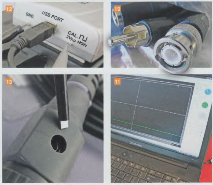
Preparation of the lead extension is a simple process and requires little skill. The three-part cable- BNC, audio RCA and DC voltage charging cable – (pic 10), can easily be separated.
The BNC is manually prised away from the other two parts and they can be discarded.
The final working unit will comprise the following for each channel:
the laptop
the processor
an extension cable per channel a BNC adaptor per channel
a probe per channel.
Two cables and two adaptors will be needed if two channels are required.
The mini CD now goes into the laptop and the prompts need to be followed.
The laptop is now converted into a most powerful oscilloscope with all the bells and whistles of a laptop and a DSO’s processing features (pic 11).
For fine tuning, connect the probe to the calibrated output signal (pic 12) generated by the processor. The calibrating tool that is not affected by EMF bombardments (pic 13) is used by inserting it into the hole and rotating it until a perfect square wave is observed.
Armed with this new theory, practice perfecting a good calibrated square wave – until the next article on oscilloscopes .