

In this article we will be covering the basic operation and the diagnostic testing of the modern 02 sensor system.
With the introduction of stricter emissions standards and consumers demanding better fuel consumption, vehicle manufacturers have been forced to monitor exhaust emissions more closely then ever.
To meet these ever increasing demands vehicle manufacturers are using more and more 02 sensors. Newer electronic management systems usually incorporate at least one sensor in the manifold before the catalytic converter and one sensor after the catalytic converter. This is how the term, bank 1 sensor 1, and bank 1 sensor 2, are derived.
Pre catalytic converter sensors are used to monitor and correct the air fuel ratio of the engine and post catalytic sensors are used mainly as a diagnostic sensor.
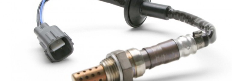
The most common types of 02 sensors used today, is the Zirconium Dioxide, to a lesser degree Titanium Dioxide.
Zirconium Dioxide: Zirconium dioxide sensors are commonly used to regulate the fueling before the catalytic converter and for diagnostic purposes after the catalytic convertor. They come in a variety of styles which may include one and two wire unheated sensors, three and four wire units with heaters.
Correct operation of these sensor requires the core temperature of the sensor to be in excess of approximately 300deg c. For this reason most manufactures now have a heater element incorporated into the sensor. When the Zirconium dioxide sensor is operating correctly it will output a voltage that will swing from around 100Mv (lean) up to 900Mv (rich) at a rate of about once per second as can be seen in Fig1.
Should a O2 sensor heater DTC code be logged in the ECU then there is a need to test the sensors heater circuit. The wiring is not always the same from manufacture to manufacture. I have included a list of colors for the NTK/NGK range of sensors:
Zirconium Dioxide Sensors: 1 & 2 Wire Sensors
Black Signal
Grey Ground
Zirconium Dioxide Sensors: 3 Wire Sensors
Black Signal
White (2) Heater Element
Zirconium Dioxide Sensors: 4 Wire Sensors
Black Signal
Grey Ground
White(2) Heater Element
Titanium Dioxide: Titanium Dioxide O2 sensors are one of the newer version of O2 sensors known as resistance or switching 02 sensor, by their very nature do not generate a voltage in the same way as the simpler Zirconium Dioxide O2 sensors.
The Titanium Dioxide sensor requires a voltage to be supplied to the sensor (approx 5volts) and the Titanium Dioxide sensing element, changes its electrical resistance as the oxygen content in the exhaust gases changes. Lean mixture equals less conductivity and the resistance rises and the voltage reduces (0.5v).
The opposite can be said for a rich mixture, as the resistance decreases, the voltage will increase (4.5v). Some advantages of the Titanium sensor are a more compact design (as they do not require an internal air reference), operating temperatures can be achieved faster and are less likely to be affected by exhaust contamination.
Below is a typical out put from a Titanium O2 sensor placed up stream of the catalytic converter.
OK so now you have a basic understanding of the types of O2 sensors and how they are used, the next step is to understand how to perform some basic testing to determine if the sensor is due to be replaces.
Testing: O2 sensor faults can be broken down into a number of sections, by far the most commonly reported fault would be heater circuit failure. So what’s the best way to diagnose a faulty heater circuit? Well simply disconnect the sensor from the wiring harness, locate the heater wiring, then using a multimeter, measure the resistance of the heater element within the sensor. The resistance should be in a range of around 4 Ohms through to around 18 Ohms. Should the resistance be outside this range you would need to question the integrity of the sensor.
Sensor response is also high on the list of reported faults. This fault can be tested very simply by feeding a small amount of carburetor cleaner into the intake and looking for an appropriate response from the sensor. If the sensor is found to be slow or unresponsive, replace the sensor.
Catalytic converter inefficiency D.T.C. is also a commonly reported fault and often linked to poor operation of O2 sensors.
Before you condemn the catalytic converter, first check the operation of both the front and rear O2 sensors.
For example, if the front O2 is operating correctly and is responding to changes in the engine mixture, but the rear O2 sensor is slow to react because of contamination (or simply because of old age) the ECU sees the difference between the front and rear as a potential catalytic converter issue.
This code can also be set if two good sensors respond to change in exactly the same way (no change in mixture across the catalytic converter)
Zirconium sensors are related to batteries. If the voltage generated by the sensor is reaching the upper limit of around 0.900Mv then there is little chance of the sensor being faulty, however if the sensor voltage is dropping to 0.00Mv there is a good chance that the sensor is faulty.
Please Note: this document is not applicable for wide band sensors.


FOR WIRA 1.5CC MMC ENGINE WHAT IS THE CORRECT OXYGEN SENCOR TO BE USE.PLS ADVISE.
WHAT BRAND OF OXYGEN SENCOR TO BE USE.