
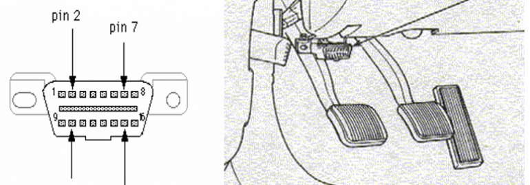
A Nissan Leaf is equipped with a Type A vehicle diagnostic connector, defined by SAE J1962 and ISO 15031-3. This connector consists of 16 pins arranged in two rows of eight with a mandated designation for nine of the pins. This connector is located under the steering column, beneath the battery and drive system. This connector is capable of receiving messages related to the battery and general vehicle operation. In addition, it also allows drivers to view information about battery health and drive system problems.
OBD port
The OBD port is a specialized connector for monitoring a variety of automotive electronic functions. Its multiple pins and wires connect directly to the ECM, or engine control module, of the vehicle. As a result, the improper installation of these devices could cause extensive damage to your vehicle. Here are a few things you should keep in mind when installing OBD connectors on your car. Read the directions carefully to ensure the proper connection.
There are ten common services available with the OBD connector. The first is Current Data, which displays real-time parameters. Other modes allow you to view and clear diagnostic trouble codes, freeze-frame data, and other data. While most cars are equipped with an OBD port, some models may not have an OBD port. For example, a vehicle with a non-OBD port cannot connect to a Geotab fleet tracking solution.
If your car has an OBD port, you will need to use a diagnostic tool that uses the OBD port. The OBD port is typically found under the dashboard panel, or underneath the steering wheel. The OBD port contains a number that will tell you what mechanical systems and functions are malfunctioning in the vehicle. Depending on the severity of the malfunction, an OBD port can trigger the Check Engine light on your car.
MaxiAP AP200
The MaxiAP AP200 vehicle diagnostic connector is an interface adapter that connects to a vehicle’s diagnostic connector and then sends the data to an Android or iOS device. This compact device also comes with a Bluetooth OBDII connector and an app. It is the perfect Do-It-Yourself tool because it is compatible with virtually every vehicle model. It offers a wide range of features that allow you to get to the bottom of the problem in minutes.
The Bluetooth-enabled MaxiAP200 device features a serial number and QR code that can be scanned to determine the problem. The diagnostic list is accessed through the diagnostic menu. The Bluetooth-enabled device will display a plus sign next to the diagnostic list. The software on the device is free of charge. However, if you need to upgrade its software, you can do so through VCI Management.
Another major advantage of the Autel AP200 is that it supports PDF format for repair reports, which is great for keeping track of the vehicle’s condition. The AP200 supports almost all 1996-and-newer OBDII-compliant vehicles, including Hyundai, Mazda, Nissan, Chrysler, and Toyota. The Autel AP200 has a Bluetooth connection that lets you connect the device to your iOS or Android device.
NEXIQ Blue-Link
If you are looking for a mobile device for vehicle diagnostics, the Nexiq Blue-Link Mini is the right option for you. This device plugs into your vehicle’s diagnostic connector and connects wirelessly to the on-board electronic control units. It is also compatible with the First-Link mobile app and can be downloaded from the App Store or Google Play. It is designed to help you and your mechanic understand fault codes and trouble codes.
The NEXIQ Blue-Link Mini allows you to connect your smartphone or tablet to your vehicle through Bluetooth. The device plugs into a vehicle’s diagnostic connector and uses wireless Bluetooth technology to communicate with the on-board electronic control units. With this device, you can read vehicle parameters and command special tests. The system also offers software development kits for Android and iOS devices. You can also get an application for your Blue-Link Mini.
J1962 Diagnostic BOB
A J1962 Diagnostic BOB vehicle diagnostic connector offers the convenience of connecting to a terminal test point located on the vehicle’s side. This connector accepts a scan tool for diagnostic measurements and is compatible with OEM diagnostic manual procedures. It has sixteen pins and is a convenient size, allowing it to be easily probed. The connector includes illuminated LEDs positioned around four mm banana sockets.
The OBD-II protocol is implemented over the CAN bus and allows for real-time visualization of the vehicle’s state. The protocol also allows for the retrieval of stored failure codes and various other vehicle variables that are important for diagnostic purposes. To find the diagnostic code of your car, you should first determine the vehicle’s make and model. Then, use the diagnostic tool to locate the connector. This will allow you to troubleshoot and repair your vehicle.
Enhanced codes
Enhanced codes are special OEM codes used in vehicle diagnostics, indicating problems that require more detailed information. These codes usually cover non-emission related failures, including ABS, HVAC, airbags and other body and electrical components. To identify an enhanced code, look for the second digit in the OBD II diagnostic connector, which is either zero or one. Enhanced codes are often used for warranty purposes and in cases of malfunction.
Currently, the only means of reading these codes is through the vehicle’s diagnostic connector. A basic code reader only displays a five-character code. To identify the cause of a specific problem, the vehicle owner must check a list of DTCs or the manufacturer’s website. A more comprehensive fleet management solution, however, provides complete code definitions and fault alerts. Both basic and enhanced code readers connect to a 16-pin OBD-II connector and use a specific adapter for pre-1996 vehicles.
The OBD port is the main vehicle diagnostic connector, and the OBD-II standard is a set of standardized DTCs. This standard was developed to improve diagnosis of emission-related vehicle subsystems. It is also the main connector for external scanning devices. The diagnostic reader sends a diagnostic request to the vehicle and the ECU responds with the appropriate DTCs. Once the response has been received, it is then displayed on the diagnostic connector.
Logging raw CAN frames
The CAN protocol has a variety of features and functions. CAN messages are typically 7 bits in length. The message is prefixed with the Start of Frame bit and contains the information on the CAN bus. CAN messages also include a cyclic redundancy check (CRC) of 16 bits. CRCC is used to detect transmission errors, and a node will acknowledge a message by overwriting the recessive acknowledge bit with a dominant one. A CAN frame may contain several subframes.
To log raw CAN frames, first you need to enable CAN RAW functionality. The ID 520 represents four diagnostic port values and is a bitwise value. The CAN RAW socket also provides a command-based configuration interface. You can use this interface to configure various settings, such as filtering CAN messages in kernel space, detecting changes in packet length, and monitoring the time-outs of received messages.
The second step involves logging CAN frame data with a computer. When logging raw CAN frames, the data is stored in a document. Once you’ve logged the data, you can filter it by changing the code, or by noting any changes that you observed in the vehicle. You can also create a logging script that takes a screenshot of the CAN bus frames. If you’re unsure of what CAN frame data contains, you can also refer to the manual to make sure it is accurate.


