|
PIDS are the serial data that can be accessed from the vehicle computer using a scan tool. PIDS include:
- Status of the OBD II System Component Monitors
(Ready or Complete, or Not Ready or Incomplete)
- Live Sensor Data
(Oxygen sensor rich/lean indication, coolant temperature, MAP value, TPS value, vehicle speed, mass air flow, ambient temperature, engine rpm, etc.)
- Status of Switches or Devices
(cruise control on/off. brake pedal switch on/off. TCC engaged/disengaged, etc.)
- Long and Short Term Fuel Trim, O2 sensor cross counts, injector duration.
DIAGNOSTIC VALUE
PIDS provide valuable diagnostic information when checking the operation or status of various sensors, circuits and switches in the vehicle's engine management system.
For example, if the MIL lamp is on and you find an oxygen sensor code, you can call up the oxygen sensor PIDS on your scan tool display to see what the oxygen sensor is telling the PCM.
You can also compare PIDS to see how one component may be affecting another.
For example, when you suddenly open the throttle on an idling engine, rpm should increase, the TPS reading should change and the MAP sensor value should drop.
PIDS can also be compared using a "graphing multimeter" or on a scope that converts the voltage values to waveforms.
Comparing the waveforms of several related sensors can help you find faults that might otherwise be impossible to detect.
SCAN TOOL PID CAPABILITY
Different scan tools have different capabilities to display PIDS.
The OEM scan tools used by new car dealers are capable of displaying every possible PID value that is built into the engine management system.
Most general purpose aftermarket scan tools do not contain the software that allows them to match the OEM scan tools in every respect -- but for most applications they can display all the important PIDS.
The trouble is you never know what PIDS are missing until you go looking for one and find it isn't there. Bummer.
That's why many professional technicians own multiple scan tools: an aftermarket general purpose scan tool, and one or more OEM scan tools for the makes they most frequently work on.
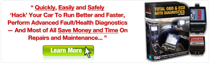
Scan tools like TOAD support various PIDS including live data values, the status of switches and other devices, the readiness status of various OBD II monitors, and other test results.
Live data provides real-time measurements of system inputs.
Statuses tell you if a switch, relay or other device is ON/OFF or has been commanded ON or OFF.
Readiness monitors tell you if the monitors have completed or not.
Test results are measured by the PCM and compared against preprogrammed pass/fail values in teh PCM's memory.
LIVE DATA:
- Air Flow Rate From MAF -- The airflow rate as measured by the mass air flow sensor.
- Absolute Throttle Position -- The absolute throttle position (not the relative or learned) throttle position. Usually above 0% at idle and less than 100% at full throttle.
- Calculated Load Value -- Indicates a percentage of peak available torque. Reaches 100% at wide open throttle at any altitude or RPM for both naturally aspirated and boosted engines.
- Engine Coolant Temperature -- Engine coolant temperature as read by the engine coolant temperature sensor. This value should be compared to the actual coolant temperature to see if they match.
You can use an infrared thermometer or other thermometer to measure the temperature of the coolant at the thermostat outlet. If the actual temperature and displayed temperature do not match, it would tell you the coolant sensor is not reading correctly.
- Engine RPM -- The current engine speed in revolutions per minute (RPM).
- Fuel Rail Pressure -- Pressure in the fuel rail when the reading is referenced to atmosphere (gauge pressure).
- Ignition Timing Advance -- Degrees of ignition timing (spark) advance for #1 cylinder (not including mechanical advance). Intake Manifold
- Pressure -- Pressure in the intake manifold derived from a Manifold Absolute Pressure (MAP) sensor.
- Long Term Fuel Trim (LTFT) -- The correction factor (percentage) being used by the fuel control system in both open and closed loop modes of operation. LTFT should typically be within plus or minus five. Positive LTFT numbers indicate the PCM is adding more fuel to compensate for a lean fuel condition.
Negative LTFT numbers mean the PCM is delivering less fuel to compensate for a rich fuel condition. If the LTFT is higher than 10 either way, it may indicate a problem.
- Short Term Fuel Trim (STFT) -- The correction factor being used in closed loop by the PCM to maintain a balanced fuel mixture. If the fuel system is open loop, 0% correction should be reported. As with LTFT, the number should usually be plus or minus five. If greater than 10, it indicates a fuel mixture problem.
- O2 Sensor Output Voltage -- The actual voltage being generated by the oxygen sensor (should be 0.1 to 1.0 volts for a conventional zirconia O2 sensor).
For wide-band O2 sensors and linear O2 sensors, the value may be higher, or it may be converted to a zero to one volt scale.
There may be multiple O2 sensor PIDS depending on homw many sensors the engien has (Bank1 sensor 1, Bank2 Sensor 1, etc.).
- Time Since Engine Start -- Shows the time the engine has been running since it was last started. Vehicle Speed -- Displays vehicle road speed as read by the vehicle speed sensor (VSS).
- Absolute Load Value -- This is the normalized value of air mass per intake stroke displayed as a percent.
- Absolute Throttle Position -- The absolute throttle position (not the relative or learned) throttle position. Usually above 0% at idle and less than 100% at full throttle.
- Accelerator Pedal Position -- The absolute pedal position (not the relative or learned) pedal position. Usually above 0% at idle and less than 100% at full throttle.
- Ambient Air Temperature -- The ambient air temperature as ready by the air temperature sensor. This value can be compared to the temperature reading by another thermometer to see if the values match. If they do not, the air temperature sensor is not reading accurately.
NOTE: the temperature reading will depend on the location of the sensor. If the sensor is located under the hood, it may read higher than the outside temperatrue when the vehicle is not moving becuase of engine heat.
- Barometric Pressure -- Barometric pressure as determined by a barometric pressure (BARO) sensor. Note some weather services report barometric pressure adjusted to sea level. In these cases, the reported value may not match the displayed value.
- Catalyst Temp -- The temperature inside the catalytic converter.
- Commanded EGR -- Tells you what the PCM is commanding the EGR valve to do.
The percentage vlue should be 0% when EGR is commanded off (at idle), 100% when EGR is commanded on (typically when cruising under light load), and between 0% and 100% is the EGR solenoid is duty cycled on and off by the PCM (depending on vehicle speed, engine load and temperature).
- Commanded Equivalence Ratio -- Fuel systems that use conventional oxygen sensor displays the commanded open loop equivalence ratio while the system is in open loop. Should report 100% when in closed loop fuel.
To obtain the actual air/fuel ratio being commanded, multiply the stoichiometric A/F ratio by the equivalence ratio. For example, gasoline, stoichiometric is 14.64:1 ratio.
If the fuel control system was command an equivalence ratio of 0.95, the commanded A/F ratio to the engine would be 14.64 * 0.95 = 13.9 A/F.
- Commanded Evaporative Purge -- This value should read 0% when no purge is commanded and 100% at the maximum commanded purge position/flow.
- Commanded Throttle Actuator -- This value should be 0% when the throttle is commanded closed and 100% when the throttle is commanded open.
- Control Module Voltage -- Power input to the control module. Normally, this should show battery voltage minus any voltage drop between the battery and the control module (which should be less than a few tenths of a volt).
Distance Since DTCs Cleared -- How many miles the vehicle has been driven since any DTCs were cleared with a scan tool. Distance
- Traveled While MIL On -- Tells you how many miles the vehicle has been driven with the MIL light on. Also tells you
how long the driver has been ignoring the light!
- EGR Error -- Calculated error as percent of actual commanded EGR. Negative percent is less than commanded and positive is more than commanded. The greater the value, the more likely the EGR valve is sticking.
- EVAP Purge -- This value is displayed as a percentage and is normalized for all types of EVAP systems. When EVAP purge is commanded off, the value should be o%, and 100% when it is commanded on.
This is an important value o check if the engine has lower than normal LTFT and STFT fuel trim numbers (indicating a rich fuel condition). The purge valve may be leaking vapor into the intake manifold.
To eliminate the purge valve as a possible source of fuel vapor, pinch off the purge vapor hose, run the engine and recheck the STFT number. If it is back to normal, the purse valve is leaking.
- EVAP System Vapor Pressure -- Evaporative system vapor pressure normally obtained from a sensor located in the fuel tank.
- Fuel Level Input -- Indicates the nominal fuel tank liquid fill capacity as a percent of maximum.
- Fuel Rail Pressure -- Indicates the fuel rail pressure at the engine referenced to atmosphere (gauge pressure).
- Fuel Rail Pressure Rel Manifold -- The fuel rail pressure referenced to the manifold vacuum (relative pressure).
- Intake Air Temperature -- The temperature of the air in the intake manifold as read by the intake manifold air temperature sensor. This should be the same as ambient temperature in a cold engine that has not been started, and should be higher than ambient tempertarue if teh engine is warm and has been running.
- Minutes Run with MIL On -- Accumulated minutes of engine run time while the MIL light is on.
- O2 Sensor Wide Range mA -- Milliamp current for linear or wide-ratio oxygen sensors.
- O2 Sensor Wide Range V -- Voltage for linear or wide-ratio oxygen sensors.
- Relative Throttle Position -- Relative or learned throttle position.
- Time Since DTCs Cleared -- Accumulated time since DTCs where cleared with a scan tool.
- Warm-ups Since DTCs Cleared -- Number of warm-up cycles since all DTCs were cleared with a scan tool. A warm-up is defined as the coolant temperature rising by at least 22°C (40°F) and the engine temperature reaches at a minimum 70°C (160°F), or 60°C (140°F) for diesel engines.
TROUBLE CODES AND FREEZE FRAME DATA
Code readers and scan tools will also display Stored Diagnostic Trouble Codes (DTCs), usually in numeric order.
Many scan tools can also display Pending Trouble Codes.
These are codes that indicate a fault has been detected, but that the fault has not yet repeated.
If the fault repeats under similar driving conditions, it will usually cause the Pending Code to become a Stored Code and turn on the MIL light.
Many scan tools can also display Freeze Frame data.
These are PIDS that are captured when a fault occurs so you can refer to them later when diagnosing the problem.
Freeze frame data typically includes related sensor values at the time the fault occurred.
STATUS AND READINESS MONITORS
OBD II requires the following status and readiness monitors:
- Fuel System 1 Status
- Fuel System 2 Status
- Secondary Air Status
- Auxiliary Input Status
- Misfire Monitor Status
- Fuel System Status
- Comprehensive Component Monitoring Status
- Catalyst Monitoring Status
- Heated Catalyst Monitoring Status
- Evaporative System Monitoring Status
- Secondary Air System Monitoring Status
- A/C System Refrigerant Monitoring Status
- Oxygen Sensor Monitoring Status
- Oxygen Sensor Heater Monitoring Status
- EGR System Monitoring Status
- ECU Oxygen Sensor Test Results
|