
|
ELM327 Review & About ELM 327 OBD2 Interface
Posted by Alex E. on 01 October 2014 04:14 PM
|
|||||||||||||||||||||||
|
Index:
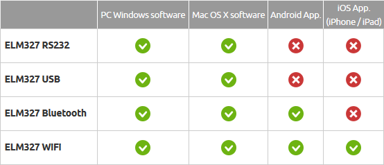
Presentation of ELM interfacesThere are several types of interface. The most common use a chip made by ELM Electronics. ELM327 is the most widely used and practical, supports all OBD protocols. IE: KWP, PWM, VPN and CAN. The other interfaces only support one protocol. For example, ELM320 only supports PWM. And ELM322 supports VPN and the ELM323 KWP. Right now, there are 4 types of ELM327 interface:
Below for illustration, is a photo of the 4 types of interface using this integrated circuit (electronic chip):
Despite appearances, these 4 interfaces are practically identical, at least electronically. Only their external aspect and the connection type differ. At their heart is an ELM327 circuit. Another thing which may be confusing is the "firmware" version. That may vary. The official versions currently in circulation are 1.3a and 1.4b, 2.1 Online, you will also find common version 1.5. We have bought one and can confirm that it doesn't exist! It is only a copy of version 1.2 masquarading as 1.5. Check out tips and advice section for how to know which ELM version you have. Where can I buy an ELM interface?
Instructions for the ELM327 interfaces1. Installing the drivers:
2. Description of LED indicators:
Operating principle of the ELM327 interface
The electronic unit contains 3 main sub-assemblies to operate the interface:
The diagram below shows the main function of an interface.
After this brief presentation, the term "interface" should mean more. The role of the ELM327 is to act as an interface between 2 different environments: the car, governed by standards with a high level of reliability and a low price, and the IT world more focussed on modularity.
Tips and advice for using ELM327 interfacesHow do I know which software version it is?The interfaces do not always have the same level of quality. As we mentioned above, the software version displayed is not always reliable. Some versions of the circuit are on sale that are not even listed by the manufacturer (reminder: ELM Electronics). User returns have taught us that some versions, that do not officially exist, are in circulation. To clarify the situation:
We do not need to go into the details as to why these non-official versions exist. What is important as a user is to be able to qualify your interface. IE: be able to verify its capacity. To do so, we recommend you do the following:
This little test will enable you to determine what level of function is installed in your interface. Even if this is only a simplified version of our complete procedure, it is effective and fast. TOAD software is 100% operational with interfaces from version 1.2, even though it uses some commands from version 1.3, there is no impact on function.
ELM circuit ELM for electronics techniciansIf your ELM interface breaks down or if you want to create your own circuit, the diagram below will help you. It shows the circuit of an ELM327 RS232 interface. The basic circuit is always the same whatever the connection mode (RS232, USB or Bluetooth). The difference lies mainly in the components connected to pins 17 and 18 of U1 (ELM327 integrated circuit). For USB interfaces, a VCP (Virtual COM Port) component is used to "convert" an RS link into USB like USB adaptor cables <-> RS232. There are currently two families of components in the ELM327. The manufacturer FTDI with the component FT232 (more details on the FTDI site) and Silicon Labs with the component CP210x (more details on the Silicon Labs website). Bluetooth interfaces use an RS modem.<->Bluetooth. WiFi interfaces use an RS modem.<->WiFi allows adhoc wireless communication.
Click on the images to enlarge In the event of malfunction: ELM Electronics has created a very good and practical application note with the voltage levels and a test procedure. This document can be found at the following address: http://www.elmelectronics.com/AppNotes/AppNote02.pdf.
| |||||||||||||||||||||||
|
|
|||||||||||||||||||||||


