|
Distributorless Ignition Systems (DIS)
Posted by Alex (Im) E. on 31 January 2013 10:19 PM
|
|
|
Distributorless ignition systems (DIS) have been around for almost a decade now, and have eliminated much of the maintenance that used to be associated with the ignition system. No distributor means there’s no distributor cap or rotor to replace, and no troublesome vacuum or mechanical advance mechanisms to cause timing problems. Consequently, DIS ignition systems are pretty reliable. Even so, that doesn’t mean they are trouble-free. Failures can and do occur for a variety of reasons. So knowing how to identify and diagnose common DIS problems can save you a lot of guesswork the next time you encounter an engine that cranks but refuses to start, or one that runs but is missing or misfiring on one or more cylinders. If an engine cranks but won’t start, is it fuel, ignition or compression? Ignition is usually the easiest of the three to check because on most engines, all you have to do is pull off a plug wire and check for spark when the engine is cranked. On coil-over-plug DIS systems, there are no plug wires so you have to remove a coil and use a plug wire or adapter to check for a spark. If there’s no spark in one cylinder, try another. No spark in any cylinder would most likely indicate a failed DIS module or crankshaft position sensor. Many engines that are equipped with electronic fuel injection also use the crankshaft position sensor signal to trigger the fuel injectors. So, if there’s no spark and no injector activity, the problem is likely in the crank position sensor. No spark in only one cylinder or two cylinders that share a coil would tell you a coil has probably failed. DIS COIL CHECKSThe coils in DIS ignition systems function the same as those in ordinary ignition systems, so testing is essentially the same. But the driveability symptoms caused by a weak coil or dead coil will be limited to one or two cylinders rather than all the cylinders. Many DIS systems use the "waste spark" setup where one coil fires a pair of spark plugs that are opposite one another in the firing order. Others, including the newer coil-over-plug systems, have a separate coil for each spark plug. Individual DIS coils are tested in essentially the same way as epoxy-filled (square-type) ignition coils. First, isolate the coil pack by disconnecting all the leads. Set the ohmmeter in the low range, and recalibrate if necessary. Connect the ohmmeter leads across the coil’s primary terminals, and compare the primary resistance reading to specifications (typically less than 2 ohms). Then connect the ohmmeter leads across the coils’ secondary terminals and compare the secondary resistance reading to specifications (typically 6,000-30,000 ohms). If readings are outside the specified range, the coil is defective and needs to be replaced. If measuring the secondary resistance of a DIS coil is difficult because of the coil’s location, try removing the wires from the spark plugs and measure secondary resistance through the plug wires rather than at the secondary terminals on the coils. Just remember to add in a maximum of 8,000 ohms of resistance per foot for the plug wires. DIS MODULE & SENSOR CHECKSHere’s a little trick that will literally show you if a DIS module and its crankshaft sensor circuit are working: connect a halogen headlamp to the spade terminals that mate the DIS module to the coils. A headlamp is recommended here because it puts more of a load on the module than a test lamp. If the headlamp flashes when the engine is cranked, the DIS module and crankshaft position sensor circuit are functioning. Therefore, the problem is in the coils. If the headlamp doesn’t flash, or there’s no voltage to the module or coil pack when the engine is cranked, the problem is most likely in the crankshaft sensor circuit. On most vehicles, a bad crank position sensor will usually set a fault code, so use a scan tool to check for a code. Or, check the crank sensor itself. Magnetic crank sensors can be tested by unplugging the electrical connector and checking resistance between the appropriate terminals. If resistance is not within specs, the sensor is bad and needs to be replaced. Magnetic crank position sensors produce an alternating current when the engine is cranked so a voltage output check is another test that can be performed. With the sensor connected, read the output voltage across the appropriate module terminals while cranking the engine. If you see at least 20 mV on the AC scale, the sensor is good, meaning the fault is probably in the module. If the output voltage is low, remove the sensor and inspect the end of it for rust or debris (magnetic sensors will attract iron and steel particles). Clean the sensor, reinstall it and test again. Make sure it has the proper air gap (if adjustable) because the spacing between the end of the sensor and the reluctor wheel or notches in the crankshaft will affect the sensor’s output voltage. If the air gap is correct and output is still low, replace the sensor. Hall effect crankshaft position sensors typically have three terminals; one for current feed, one for ground and one for the output signal. The sensor must have voltage and ground to produce a signal, so check these terminals first with an analog voltmeter. Sensor output can be checked by unplugging the DIS module and cranking the engine to see if the sensor produces a voltage signal. The voltmeter needle should jump each time a shutter blade passes through the Hall effect switch. If observed on an oscilloscope, you should see a square waveform. No signal would tell you the sensor has failed. DIS PERFORMANCE PROBLEMSIn instances where the engine starts and runs but does not perform well (lack of power, poor fuel economy, spark knock, elevated emissions, etc.), the problem may be outside the DIS system. First, the individual coils should be tested to make sure their primary and secondary resistance is within specs. If the coils are all okay, the electronic spark control circuit may be receiving bad information from some of the engine’s other sensors. Low MAP sensor output voltage or a coolant sensor that reads cold all the time will allow more spark advance than normal. This, in turn, may cause detonation (spark knock) problems when the engine is under load. So too can a faulty knock sensor or an EGR valve that isn’t working. High MAP output voltage or a misadjusted throttle position sensor can have the opposite effect and cause the spark control system to retard timing more than normal. Retarded timing will reduce performance and fuel economy. Don’t forget, too, that ordinary secondary ignition problems can also cause misfires with DIS the same as a conventional ignition system. A bad spark plug wire or a worn or fouled spark plug will act just like a weak or bad DIS coil. So anytime you find an ignition problem that is isolated to a single cylinder, remove and inspect the spark plug and plug wire to rule out those possibilities.
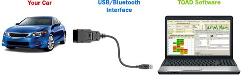
TIP: Tune Your Car with Powerful Diagnostics Software
Whether you're a home car owner or an auto mechanic — you can save thousands of dollars on car maintenance, save time and effort on repairs, and dramatically improve your cars lifespan/performance — by getting yourself a professional car diagnostics scanner. They're called OBD scan tools. And will give you an instant overview of your vehicles condition by tapping into it's computer chip. But more importantly, you can also obtain software that will allow you to edit the cars performance data. Like adjusting RPM, fuel injection, etc. This is what car performance shops charge thousands of dollar for — to allow the car to operate more fuel efficiently, faster or with stronger torque/BHP. The good news is, you can do the same at fraction of a cost, with a USB connection interface to your laptop, and car tuning software. We suggest you Google on this to discover more. Or you can get this car diagnostics/tuning package here. | |
|
|
|