

INTRODUCTION
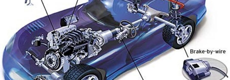
- Vehicle technology has seen rapid change
- Skills shortage in diagnostics and troubleshooting
- Problem analysis and diagnostics have become highly sophisticated and specialised
- Diagnostic skills encompass both mechanical and electrical diagnostics. Vacuum gauges, compression gauge and cylinder leakage tester, fuel pressure and flow testers, gas analysers
- Technicians now require an understanding of electrical theory and circuits
- Electrical diagnostics is becoming impossible without the correct diagnostic equipment, vehicle data and information
- Typical electrical test equipment required to assist in diagnosing faults are scan tools, electrical connector test equipment, digital multimeters (DMM) and oscilloscope
- Common-cause and common-mode failures are those that can affect multiple systems at once
- A good fault finding model captures information that allows faults to be reasoned about in a systematic way
- Technicians often lack accurate diagnostic information together with time pressures, and revert to a shotgun troubleshooting approach – it is easier to repair a problem if you have a clear understanding of how it works when it’s not faulty
What is your APPROACH when Diagnosing Customer Vehicles?
A Attitude
P Patience
P Preparation
R Research
O Organised
A Advice
C Communication
H Habit
Case One
Suzuki Grand Vitara 2005 V6 2.7
Vehicle was in for a clutch replacement. After the clutch was fitted and the system bled, unable to get a good clutch pedal. The system has a concentric clutch slave cylinder which was supplied with the clutch kit.
Use the brakes hydraulic system to reverse bleed the clutch hydraulic system.
Use nearest brake caliper, attach a hose between the brake caliper bleeder and the clutch slave cylinder bleeder. Open both bleeder nipples and slowly depress the brake pedal to reverse bleed the clutch system.
Case Two
Toyota Hilux 2008 GGN 25R V6 1GR-FE
Vehicle was intermittently cutting out. The vehicle would restart OK then cut out about 10 seconds later. Testing voltage to fuel pump revealed 9 volts with vehicle running.
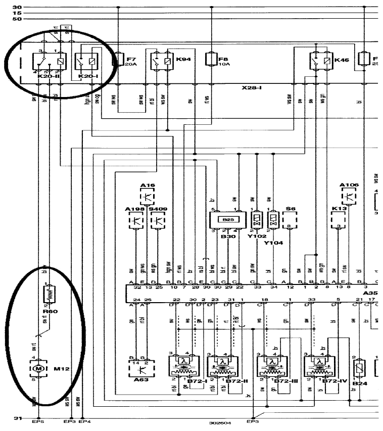
Wiring Diagram
Case Three
Mazda 121 1995
Vehicle towed in with suspect fuel pump issue Vehicle had new fuel pump fitted a few weeks earlier Possible causes,
Harness or connections Fuel pump relay
Fuel Quality ECU
Testing, both power and earth
Case Four
Toyota Hilux KUN26R 2007 1KD-FTV
Third engine being fitted due to damage to number one cylinder. Unable to program injectors.
No communication with vehicle.
CAN bus crashed. Inspection of the OBD connector revealed no pins in 6 and 14, therefore no high speed bus.
Locating a vehicle with the same set up and plugging in a CAN test break-out box showed communications on pin 11.
After accessing a wiring diagram and tracing pin 11 from the OBD connector found the circuit going to the SRS ECU.
Located SRS ECU and found water damaged.
Replacement SRS ECU fitted and full communications were back. It was then possible to reprogram the injectors to the new engine.
Part replacement
After replacing a faulty component, sometimes you find found the part still does not operate. Some electronic systems are protecting the circuit and the ECUs by isolating the circuit and logging a fault code. Scanning the vehicle’s electronic systems will enable you to find the fault codes and clear them.
Components include washer pumps, headlight globes, park light globes, horns, ale compressors.


